
© 2009 Er. Jagvir Goyal
Note: This highly informative and elaborate paper was written by the Author many years back and holds valuable information. Readers should update themselves with the latest developments that might have occurred after the presentation of this paper.
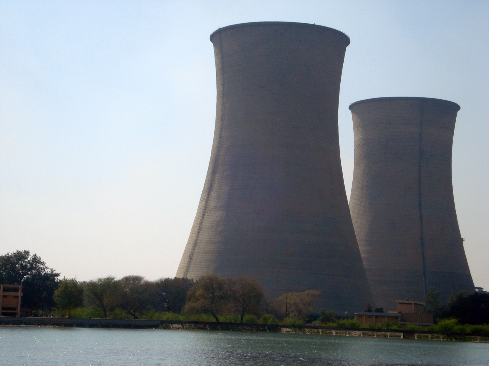
All thermal power stations need cooling towers. These are required to bring down the temperature of the water being circulated around the plant machinery. During circulation, the water draws heat from the machinery and gets hotter. Hot water is brought to the cooling towers where it is made to lose heat and become fit for re-circulation around the machinery. Cooling towers can either be natural draft cooling towers or induction draft cooling towers. In the first kind, natural air draft is used to run across water to cool it while in the latter type, draft is induced by use of fans and machinery. For thermal power projects, the quantity of water being very large, natural draft cooling towers are preferred. These are almost maintenance free structures.
Majestic structures: Natural draft (ND) cooling towers are majestic structures. These in fact have become a symbol of power stations in the world. Their sheer size and shape make them exceptional. Their design involves considerable structural and thermodynamic analysis and studies. Model studies need to be conducted before evolving their design and to ensure their performance. A decrease in their efficiency from the designated range may render them unfit. During design, it is doubly checked that the cooling tower is able to decrease the temperature of water by more than required.
Components of a ND Cooling tower: Following are the main components of a natural draft cooling tower:
- The foundations
- The cooling water basin
- The column pedestals
- The raker columns
- The shell
- The fill supporting structure
- The fill
- The water distribution pipe network
- The spray nozzle network
- The lighting system
- The lightening protection system
- The top platform
- The ladders and access platforms.
Construction Equipment for foundations: Cooling towers are of large size, having a diameter in the range of 100 metres at the bottom. Their foundations have still larger diameter, in the range of 120 metres. For such a large area of foundations, mostly, raft foundations are found suitable. Only under exceptional circumstances when the soil conditions are not good, pile foundations along the periphery of cooling towers are chosen for provision. Depth of raft foundations is kept around 3 to 4 metres.
Hydraulic excavators: Area of foundations being quite large and depth being 3 to 4 meters, hydraulic excavators are most suitable to excavate the large sized pit to require depth. Whenever hydraulic excavators are used, care is required to be taken to ensure that the bucket of the excavator doesn’t cut the ground below the required depth. Otherwise, this extra cutting of soil is required to be filled with concrete to provide a solid base to foundations. In addition, Tippers are constantly required with the excavators for transportation of excavated soil to a suitable place for its disposal.
Bar cutting and bending machines: Steel reinforcement to be placed in the foundations is large and it is better to use bar cutting and bending machines for this work. The same machines can later be used in preparing the reinforcement for cooling tower shell.
Concrete batching plant: It is generally not possible to pour the whole of cooling tower raft in one pour due to its large size. The raft is therefore divided into segments and poured either by supply of concrete from an existing concrete batching plant or by use of 4 to 5 concrete mixers for each segment. Needle vibrators are constantly required for compaction of concrete in foundations. Generally, M 20 concrete with low workability is used in foundations. Therefore. Some spare vibrators run with petrol and extra needles should always be kept to ensure proper compaction of concrete in foundations.
Construction equipment for pedestals: Concrete pedestals are located on the top of circular raft for the cooling towers to provide a solid base to the inclined columns rising to the bottom of the shell and to create an air inlet area. The pedestals are small structures involving around 100 cubic metres of concrete in each pedestal. Their number varies depending upon the number of pairs of inclined columns. Each pedestal can be well completed by using the bar bending and cutting machines for reinforcement and concrete mixers for producing concrete. Steel formwork is used for these pedestals to minimize the leakage of slurry.
Construction equipment for inclined columns: Inclined towers of a cooling tower are the most typical component, to be built with high precision. A slight change in their inclination alters the line of transfer of load from the shell to the foundations and upsets the design calculations. The inclined columns are inclined sideways as well as to the inside. Therefore, their lay out should be laid by using high precision optical instruments. Pipe scaffolding network is erected on firm ground to firmly support the shuttering for these columns. Steel forms cutting the section in two halves are fabricated and used for them. These U-shaped or semi-circular forms are easy to remove at the time of removal of forms. The forms have end flanges to be bolted in a tight manner to make them leak proof.
Construction equipment for first lift of shell: A ring beam over the inclined columns constitutes the first lift of cooling tower shell. It needs to be built in a conventional manner. This lift in fact acts as a starter for laying further lifts of cooling tower shell by use of special formwork. For the first lift, conventional scaffolding pipes and clamps are used to support the steel shuttering and the working platform. Steel forms bent to match the true curvature of the shell are fabricated for the inside and outside face of shell. The ring beam for the full tower can be laid in one go if sufficient equipment and formwork is available for the same. It is preferable to lay it in one pour for having a monolithic ring beam and for effective transfer of stresses. The equipment required to lay the concrete of the ring beam includes Scaffolds/staging pipes, rigid and swivel clamps, joint pins, trough pins, base plates for pipes, vertical steel shuttering fabricated to suit the inner and outer curvature of shell, steel plates for bottom of the ring beam, turn buckles and side supports to keep the inner shuttering in position during pouring of concrete and to resist concrete pressure, friction hoists to lift the buckets full of concrete to the working platform, concrete mixers and needle vibrators, optical instruments to check the alignment and curvature of the ring beam and buckets and trolleys for concrete transportation.
Construction equipment for columns and beams: A cooling tower houses a large network of RCC columns and beams to create the supporting structure for the cooling fills to be provided below hot water inlet level. The level of entry of hot water inside the cooling tower is at around 10 to 11 metres above the ground. The cooling fill is about 2 metres below the level of its entry. Thus the fill base is about 8 to 9 metres above the ground level. Adding the depth of basin from the base of which the supporting columns are to rise, the length of columns is in the range of 11 to 12 metres. Columns are mostly rectangular in section and erected at pre-decided locations to create a network of beams at fill level. The equipment required in the pre-cast yard for RCC columns and beams includes steel moulds of required sections and lengths of columns and beams, bar cutting and bending machine for preparing the reinforcement for beams and columns, tilting type concrete mixers equipped with hoppers, concrete carrying trolleys, needle vibrators, extra needles, curing arrangement set up including installation of a deep bore well, provision of submersible pump, GI pipe network for distribution of water and hose pipes for manual sprinkling of water on the gunny bags covering the pre-cast RCC members and mobile cranes of 10 t capacity to lift the pre-cast members from the pre-cast yard and their unloading in the stacking cum curing yard. The cranes can be wheel mounted or crawler mounted though the latter ones are preferred. Also, low level steel trolleys for carrying the pre-cast members from pre-cast yard to stacking yard, 25 tonne capacity trailers for transportation of pre-cast columns and beams from stacking yard to the inside of cooling tower, friction hoists and manual winches for erection of RCC columns and beams inside the cooling towers and additional mobile cranes, 2 no. or more, inside the cooling towers for unloading of pre-cast members from the trailers to the ground are required.
Construction equipment for shell construction: Total volume of concrete to be laid in the shell is worked out and the equipment required is decided accordingly. The construction of cooling tower shell was earlier done by conventional method and it used to take long construction period. These days, jump forms are used for the construction of shell. There is no need of removal and re-fixing of shuttering plates. These slide up, both on the inner and outer faces and are adjusted to suit the new inner and outer radii of cooling tower. After the initial few lifts which require heavy concreting due to large diameter and thickness, all further lifts can be laid in a single day for full periphery of cooling tower. This arrangement results in construction of a 120 metre high cooling tower in 4 to 5 months thus saving a substantial time period. Major components of jump form equipment for the shell are explained below:
Jump forms: Jump form equipment can be adjusted to suit uniform as well as variable dimensions. The dimensions can increase or decrease as the structure is built. As the dimensions of a cooling tower decrease up to throat level and increase thereafter, jump formwork suits it best because of the facility it provides for adjustment to suit the required parameters. Jump formwork has telescopic railings provided on each deck to accommodate the reduction or increase in perimeter. Similarly, the deck planks can also be adjusted. Top portion of the equipment is kept in traveling form so that the concrete-pouring deck could be adjusted and locked in a position near the periphery of the structure. Diagonally installed spindles can adjust the formwork to suit the actual profile of the structure.
Jump forms take support for climbing from the structure itself and no scaffolding pipe network is required to support them from the ground. Nor any layers of brackets are required as used in conventional formwork. Anchor bolts are provided in the walls of the structure, removed and re-fixed as the equipment rides up. Vertical Rails are fixed all around the perimeter of the structure and the equipment keeps riding up on these rails. Fixing up of these rails is a continuous process and has to be ahead of the upward movement of the equipment. The task seems to be simple but needs extra vigil for no problems or bottlenecks.
The five decks: A five deck system is created in jump formwork in comparison to three deck system in slip forms. The top deck facilitates concrete placement and reinforcement binding work. The second deck is the main working deck for fixing shutters, anchor bolts, form supports and sliding shutters. The work of alignment to the designed profile of the structure, checking of parameters such as height, radius, curvature and thickness is also carried out from this deck. The third deck allows rail extension for upward movement of equipment. Fourth deck is for operation of hydraulic jacks and to ensure that the equipment rigs are well locked in position. The fifth and last deck provides platforms for smooth finishing and painting of the structure. This five tier system is provided both along the inside as well as outside surfaces of the cooling tower.
The hydraulic system: The peripheral area of the cooling tower is divided into suitable number of segments with centre to centre spacing ranging from three metres to eight metres. It decides the number of hydraulic rig units to be used. Each rig unit consists of a structural formwork required to support the five deck system, the shuttering formwork and the hydraulic circuit. The rig members include frames, holders, girders, longitudinal beams and bracings, handrails, climbing rails and other steel sections and accessories. The structural framework units hang on to the rail tracks by means of cradles. Rail tracks are fastened to the structure being built by use of anchor bolts. Cradles ride up along the rails as and when the hydraulic circuit is operated, taking along with them the whole of the structural framework. Each such framework carries two separate hydraulic jacks that can be operated independently or jointly. In one stroke, the equipment rides up by about 30 cm. Each stroke hardly takes three to four minutes to operate. Power packs to operate the hydraulic jacks are stationed on the lower most deck. The number of jacks to be operated by a power pack depend upon its capacity. However, it is feasible to operate 15 to 20 jacks through one power pack.
Hydraulic power packs: Each power pack operates 15 to 20 hydraulic jacks. It is equipped with an electric motor of about 10 HP, 415 Volts, 3 phase of reputed make such as Crompton or ABB. The hydraulic pump has to be gear type, Bosch or such make with a flow capacity of 25 to 30 litres per minute. The power pack should have a water cooler or heat exchanger and oil filters in the return line. Oil distribution and directional control valves should also be available in the pack. Oil tank of 200 litre or such capacity should be provided. Other accessories such as Motor starter of good make such as L&T, return line filter, breather, suction strainer, level gauge, pressure gauge, gear coupling, internal piping and fittings should be provided with the pack to make it fully functional. Power packs hold the power to operate the jump form equipment and must be sturdy, trouble free and maintenance free. These should be well painted with industrial enamel paints to save them from rust.
Hydraulic hoses: The hydraulic hoses used for transmission of hydraulic oil to the hydraulic jacks and back to the pack should be tested under double the working pressure. The bursting pressure shouldn’t be less than four times the working pressure. Generally, ½ inch internal diameter hoses are used. The brand such as Swastik or equivalent should be clearly specified. The hydraulic connections should be galvanized and fully tight.
Hydraulic jacks: Hydraulic jacks used should be double acting. The working pressure, cylinder inner bore size, the stroke length, the ram diameter and the required jack capacity such as 6 to 10 tonnes should be worked out before providing jacks for the system. The jacks are provided both on inner as well as outer faces and hold the key to successful and trouble free working. A few spare jacks should be kept at site for replacement of leaking jacks as such jacks refuse to take pressure or load.
Equipment for concreting work: Either a tower crane can be provided at the centre of the cooling tower for transportation of concrete and materials to the working deck or diametrically opposite access towers can be raised to facilitate concrete transportation to the top and to allow upward passage to the workers. A small passenger hoist can also be accommodated in these scaffolding towers. Suitable arrangement can be made at the ground by positioning two or three mixers at each concrete production point. The mixers can be located at ground level and provided with chutes to directly unload the concrete in a common bucket placed over a low platform trolley moving on rails. The trolley can be moved on the rails to the hoist point from where the buckets can be hoisted up to the working deck. Such an arrangement can prove highly convenient and efficient.
Access towers: In case access towers are created at site for hoisting of concrete buckets, passenger hoist and to accommodate access ladders, huge quantities of scaffolding pipes and clamps are required. The length of scaffolding pipes is generally six metres, these are load bearing, C class, heavy duty, 48 to 60 mm in diameter and in true plumb. Horizontal scaffolding pipes and diagonal bracing pipes are also required. Rigid and swivel clamps are required in lacs in number. Base plates for verticals are required to give them wider area for dispersion of load. End to end pipe couplers are required to extend the verticals with the increase in height of shell. Two friction hoists are required to run the concrete buckets to the unloading platforms created at the top and one hoist is required for lifting of materials. In case tower crane is available, these can be avoided. The hoists are 5 to 7 tonne capacity, single drum type, equipped with magnetic brakes and using 16 mm diameter ropes. 16 to 22 mm diameter wire ropes are additionally required as guide ropes for the concrete carrying buckets. D-shackles, U-clamps, two sheave pulleys are also required to complete the running arrangement.
Passenger hoist: One passenger hoist is required to transport the engineers and workers to the platforms and back to the ground level. The passenger hoist should always be double drum type with magnetic brakes, overload alarm and limit switches as safety guards. 22 mm diameter wire ropes should be used to run the passenger cage. Guide ropes should keep the cage in position to avoid its extra swing or accident.
Equipment at top deck: At the top deck, concrete unloading arrangements are required to be created by observing special safety measures against swaying of buckets before tilting them or opening their bottom flap. The scaffolding tower is well anchored to the completed portion of cooling tower and the platform receiving concrete is well supported.
Perforated pipes are fixed along the outer and inner surfaces of cooling tower to sprinkle water on the completed portions. Booster pumps of 25 HP or so should be installed on the water tanks to lift water to higher levels. Concrete vibrators are stationed on the working deck to fully compact the concrete laid in the shell lifts. Plenty of spare needles should be kept available as the needles often need repair and replacement during construction. Plate or form vibrators are avoided as the work is carried out at very high levels and high vibrations are not to be allowed.